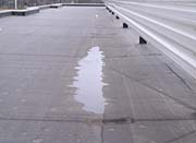
Detriments of Standing Water
The elimination of accumulated moisture from the roof’s surface is vital to the success of a low-slope roof system. Most low-slope roof system manufacturers require that the roof surface be free of all rainwater within a specified period of time for their warranties to be valid. A common industry standard is that the accumulated moisture must be gone from the roof surface within 48 hours of a rainfall. Standing water that remains beyond this time period poses serious threats to the roof system.
The most serious (and least likely) consequence is structural damage. Standing water can be deceptively heavy and the added weight of the water causes the roof to exceed the design load, possibly leading to collapse. Structural damage to this extent often occurs after a heavy rainfall on a roof that does not have adequate slope or proper drainage.
A more common consequence of standing water is membrane degradation. Standing water can rot the membrane because it leaches oil from bitumen in asphalt-based BUR systems and decreases mil thickness in single-ply assemblies. Once the membrane has been reduced to a vulnerable stage, the possibility of moisture penetrating into the system increases. Moisture intrusion is especially prevalent at all membrane imperfections. Fishmouths, splits, bare felts, open seams and unsealed felt laps are all areas where water can penetrate into the system. If water is ponded over any of these imperfections moisture will find a way into the system.
Once moisture has entered into the system it never completely dries. Wet insulation will deteriorate over time and can contribute to premature system failure. Moisture in the system also detracts from the insulation’s thermal and structural integrity. The loss of insulating value and heat resistance adds to a building’s heating costs. The presence of constant moisture could contribute to the need for deck repair or replacement in these areas, adding significant expenses to roof replacement costs.
Adequate Slope Requirements
Adequate slope and drainage must be taken into account at the design stage. Often it is infeasible to correct improper slope and drainage on an existing system due to financial considerations and impractical elevation changes. Therefore, designing a suitable slope and drainage system at the outset is not only the most economical solution, many times it is the only solution.There is no single slope that will provide for proper drainage on all roof systems. The designer should take a number of conditions into account. Particular consideration must be applied to the structural framing of the roof, the deck type, the roof membrane specification and the building layout.
The recommended minimal slope for aggregate-surfaced systems is 1/4-inch slope per foot. This is acceptable because there are many building industry imperfections and this measurement contains a tolerance for them. A building on which construction is closely monitored and has few imperfections could allow for a 1/8-inch-per-foot slope. A smooth-surfaced roof system warrants a 1/2-inch-per-foot slope.
Deck deflection and drain placement are also important considerations when determining roof slope. The deck deflection must be limited to no more than 1/240 of the roof span. This is of critical importance to accommodate the stress of either concentrated or uniform loading. Drains should always be located at the mid span because these are the points of maximum deflection. Therefore, if the deck span is 50 feet, the deflection should not be more than 2 1/2 inches (1/240 of 50 feet).
Placing drains at points of minimum deflections, such as columns or bearing walls, should be avoided due to loading conditions. However, if drains are required to be placed at columns or bearing walls, the slope of the roof must be increased. Increasing the slope will compensate for the minimal deflections in these areas. The allowable deflection will remain 2 1/2 inches, but an additional 5 inches of roof slope must be provided to keep the deck level at the mid span under maximum loading conditions.
Drainage Systems for Low-Slope Roofs
Before proper drainage methods can be determined, the type of system must be specified. There are two types of drainage systems for a low-slope roof: peripheral and interior. The designer must determine what is best for the roof system, the building layout and the climate.In a peripheral drainage system, the slope is designed to allow drainage from elevated interior areas to peripheral low points. Accumulated moisture is eliminated through scuppers and leaders located outside of the building. In mild climates where winter temperatures remain above freezing, the peripheral drainage system has been effective.
However, in colder climates, this system has experienced a number of drawbacks. Peripheral drainage systems are significantly reliant on outside temperatures. The freezing weather hampers the ability of the moisture to flow freely to the drainage areas and obstructs the system. This allows accumulated moisture, in the form of ice and snow, to remain on the roof surface for extended periods of time. The peripheral drainage system also requires more elaborate flashings to protect the gutter and scupper areas from erosion. These areas are also more vulnerable to ice damning and metal distortion from freeze-thaw cycles.
In the interior drainage system, accumulated moisture flows from elevated peripheral areas to interior roof drains. The water flows through a leader, which conducts the water through the interior of the building. The leader is connected to columns the majority of the time. There are several advantages to this type of drainage system. The most distinct advantage is that because the drainpipes are located on the building’s interior, they are constantly heated. This allows the rainwater or melting snow to flow through the system throughout the entire year.
Proper Drainage Requirements
Once the drainage system is determined, the designer must ensure positive drainage by correctly positioning the roof drains. A good rule to follow is to provide two roof drains for a total roof area less than 10,000 square feet. An additional roof drain should be added for each 10,000-square-foot area. The drains should be placed at a maximum of 75 feet in each direction away from each other. The only exceptions would be drains that are placed around obstructions, such as penthouses, HVAC equipment, skylights or similar penetrations. Drains should be placed in these areas because water does not have the ability to turn corners in an effort to flow to the drain.The most dependable type of roof drainage design is the inverted pyramid pattern. This type of pattern is particularly useful on buildings that are easily divided into rectangular areas. The premise of the pattern is that a drain is positioned in the center of the rectangular area and there is a four-way positive slope into the drain. Tapered insulation could be used to create this type of slope or it could be field-built with roof framing systems such as wood, or cast-in-place or lightweight concrete.
The drain should be recessed below the roof surface. This can be accomplished by setting the head of the roof drain below the insulation level and by providing a sump at the drain. Tapered insulation panels should be installed around the drain to ensure positive flow of water toward the drain. The tapered insulation also serves as prevention against condensation.
Drainage Details
Adequate deck slope, efficient deck deflection and the proper placement of drains are major attributes to successful roof drainage. However, there are a number of design details that are also important. These often-overlooked specifications could be the difference between a successful or unsuccessful roof system.Drains should not be placed near base flashings. The water that builds up around the drains exposes the flashing seams and could be a source of moisture intrusion into the system. Base flashings should always be located at high points to prevent water from building up around them. Drains should always be located at low points, a relatively logical concept that is not always adhered to. When a situation arises where a drain must be placed in a flashing area, or around a unit or curb, crickets should be considered. The cricket will allow water to flow freely away from the flashing towards the drain.
A drawback of crickets and saddles is that if they are improperly applied, water tends to accumulate at their sides. In essence, the only result is the transfer of the ponded area.
The roof drain area is vulnerable to moisture penetration because of the constant water buildup. The drainage area is the second most common area for roof leaks. Due to this fact, corrective actions should be taken to guard against moisture penetration. The membrane plies should extend to the inside of the roof-rain bowl ring to secure proper coverage in this area. Drain detail should be completed in accordance with the membrane manufacturer’s requirements.
The best way to guard against leaks at the drainage areas is to accommodate for differential movement between the drain and the roof deck. The roof system must have the ability to move as a unit, requiring strong securement of the roof drain to the roof deck. Secure the drain ring over the completed membrane. This will prevent wind uplift. The drainpipes need to be flexible enough to move in all directions, so that there if there is any type of movement in the drains the pipe will move with it.
A common cause of drainage failure is the accumulation of debris that enters the drain and causes a system backup. This can be prevented in a number of ways. The first way is to secure a strainer over the drain to act as a protective covering. The strainer should be fitted to match the drain and strong enough to withstand weathering elements. Annual maintenance inspections should be conducted to make sure drains are free-flowing and not clogged with debris.
The best way to avoid drainage debris on aggregate or ballasted surfaced systems is to install a gravel stop around the drainage area. A 1-foot-by-4-inch gravel stop fabricated from .032-mil finish aluminum or 16-ounce copper should be secured to the membrane surface at a minimum 3-foot diameter around the drain.
As roofing contractors you may not have direct input in initial drainage design, however, your input at as-built conditions could be valuable. By stressing the importance of proper drainage design you may avert future problems, which, in turn, eliminates callbacks on projects and helps your bottom line.
Looking for a reprint of this article?
From high-res PDFs to custom plaques, order your copy today!
.webp?height=740&t=1781278983&width=auto "KEE(2).png")


