TECHNICAL DETAILS: How to Accommodate Differential Movement
Differential movement occurs when independent structural components are adjoined at different parts of the building. These conditions can occur in roof systems at flashings, penetrations, adjoining roof areas and mechanical penthouses.

The roof system assembly is comprised of a series of materials that have to interact with other building components. This interaction of different materials and separate components increases the probability of stress fractures and openings created by differential movement. Differential movement occurs when independent structural components are adjoined at different parts of the building. These conditions can occur in roof systems at flashings, penetrations, adjoining roof areas and mechanical penthouses.
In cases where the structural deck is independent of the wall, flashings must only be anchored to the roof deck. This is accomplished through the creation of a roof-to-wall expansion joint. This detail is required in all cases where there is a possibility of differential movement between the deck and the vertical wall. A vertical and horizontal wood blocking should be formed at the base of the deck and anchored solely to the deck with the appropriate fasteners at a rate of one every 24 inches on center. The flashing system should be applied to the wood blocking. Compressible insulation should be placed in the opening between the wood blocking and the vertical wall. A metal counterflashing system should then be applied over the flashing system and anchored to the vertical wall with the appropriate fasteners at a rate of one every 24 inches on center. The counterflashing should be fabricated to allow for movement.
Some of the requirements for proper curb assemblies include the following items:
• The curb should be fabricated of a minimum 16-gauge continuous metal.
• A 2-inch wood nailer should be mounted to the top of the curb for flashing attachment.
• The curb should be a minimum of 8 inches above the finished roof surface for proper flashing height.
• There should be no openings in the side of the curb for penetrations.
• Proper waterproofing is required to seal the unit to the top of the curb.
In the case of smaller penetrations (pipes, wires, conduits, supports, etc.) a pitch pan should be installed. Pitch pans should be fabricated from 24-gauge metal and should be a minimum of 4 inches in height and 4 inches in width. The pitch pan should be filled with cement grout or Portland cement on the bottom with a top layer of pourable sealer. To avoid annual maintenance, an umbrella cover is recommended.
In addition to application at natural building separations, expansion joints are required at all roof locations that could exhibit differential movement. Their inclusion is mandatory at the junctures where decking changes - such as from metal to concrete, for example - and at junctures where structural steel, steel framing or decking change in the span direction. Expansion joints are required in these areas to eliminate stresses to the membrane that could lead to the detrimental effects such as cracking and splitting.
Expansion joints should also be provided wherever additions are connected to existing buildings or where there is a change in the interior heating conditions, such as a heated office adjoining an unheated warehouse. They should also be installed at canopies and at separate wings of “L,” “T” or “U” configurations.
Expansion joints are constructed of a minimum 1-inch wide separation that continues through the entire building from the rooftop to the foundation. Since independent movement of each building segment is required, double, parallel columns and beams are constructed on each side of the expansion joint to provide proper structural capacity. Proper detailing and application of expansion joints at the roof component is required to eliminate splitting and water intrusion at these openings. The most important design aspect of the expansion joint is that it must extend across the entire width of the roof area. Expansion joints that terminate short of the full area width or erroneously provide openings for drainage will fail to accommodate expansion and contraction, creating membrane openings that could lead to roof failures. An expansion-contraction provision should also be considered at parapet walls where the expansion joint terminates.
Similar to flashing requirements of all other roof penetrations, an expansion joint should be designed and constructed to raise a minimum of 8 inches above the roof surface. This can be accomplished by installing a proper size wood curb nailer at each side of the expansion joint. For example, if 3 inches of insulation are applied in the roof system, the wood curb nailer should be a minimum of 2 inches by 12 inches. The wood curb nailer is applied vertically to each side of the expansion joint and is connected to a 2-inch by 4-inch wood nailer that is fastened to the existing decking every 24 inches on center. A wood cant strip with a 45-degree angle is secured over the horizontal wood nailer and to the vertical wood nailer to provide structural strength and also to create proper slope for the flashing application. It is also recommended that the top of each vertical wood nailer be chamfered to the outside to allow for drainage away from the expansion joint opening. Expansion joints applied without proper curbs at each side - or at all - are improper and will lead to roofing failure from membrane splits at these points regardless of the type of membrane.
A flexible vapor retarder is applied over the vertical wood nailer into the expansion opening to hold the compressible insulation in place. The insulation is provided to prevent condensation and the formation of ice from vapor that migrates from the warm interior space. If the insulation is not applied, there is a chance that condensation from the expansion joint metal could drip into the interior space.
The most critical application component of the expansion joint is the covering. The covering serves as the waterproofing protection and it provides for proper expansion and contraction in this area. The proper covering must allow for building movement in both directions. I recommend the use of a covering fabricated from 24-gauge galvanized metal or similarly approved metal in these applications. The metal should be fabricated with a standing seam or continuous cleat to accommodate movement in accordance with NRCA and SMACNA details. Flashing of the expansion joint should be completed in accordance with NRCA details and the membrane manufacturer’s latest printed specifications.
Best practices also require the separation of the metal from the membrane surface. These materials have different expansion-contraction coefficients and could lead to membrane splits from the movement. This is predominant at gravel stops in colder climates. Separation of these materials can be provided with a layer of adhesive between the surfaces or the installation of a wood nailer.
The roof system assembly is comprised of a series of materials that have to interact with other building components. This interaction of different materials and separate components increases the probability of stress fractures and openings created by differential movement. Differential movement occurs when independent structural components are adjoined at different parts of the building. These conditions can occur in roof systems at flashings, penetrations, adjoining roof areas and mechanical penthouses.
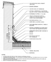
Figure 1. Base flashing with surface-mounted counterflashing at a high wall with single-ply membrane. (Detail courtesy of the NRCA.)
Flashings
The effects of differential movement are most prevalent at flashings because oftentimes walls are not anchored to structural decks. This condition exists at building additions and is typically identified by a gap (approximately 2 to 6 inches) between the roof deck and the vertical wall. Defects to flashings created by the independent movement of the materials result in diagonal wrinkling. Diagonal wrinkling is illustrated with a consistent pattern of wrinkles in the flashing that extend down from the top of the wall through the center of the wall. These types of distress patterns create vulnerable conditions including flashing separation, punctures, splits and mechanical damage.In cases where the structural deck is independent of the wall, flashings must only be anchored to the roof deck. This is accomplished through the creation of a roof-to-wall expansion joint. This detail is required in all cases where there is a possibility of differential movement between the deck and the vertical wall. A vertical and horizontal wood blocking should be formed at the base of the deck and anchored solely to the deck with the appropriate fasteners at a rate of one every 24 inches on center. The flashing system should be applied to the wood blocking. Compressible insulation should be placed in the opening between the wood blocking and the vertical wall. A metal counterflashing system should then be applied over the flashing system and anchored to the vertical wall with the appropriate fasteners at a rate of one every 24 inches on center. The counterflashing should be fabricated to allow for movement.
Roof Penetrations
In order to prevent differential movement at most roof openings, curbs are required. Proper curbs applied at roof openings negate differential movement by isolating base flashings from counterflashings and the roof penetration from the membrane. The curbs also serve as stiffeners for additional structural support around openings in plywood and metal decks. This prevents membrane damage that can be created by wind or other lateral forces.Some of the requirements for proper curb assemblies include the following items:
• The curb should be fabricated of a minimum 16-gauge continuous metal.
• A 2-inch wood nailer should be mounted to the top of the curb for flashing attachment.
• The curb should be a minimum of 8 inches above the finished roof surface for proper flashing height.
• There should be no openings in the side of the curb for penetrations.
• Proper waterproofing is required to seal the unit to the top of the curb.
In the case of smaller penetrations (pipes, wires, conduits, supports, etc.) a pitch pan should be installed. Pitch pans should be fabricated from 24-gauge metal and should be a minimum of 4 inches in height and 4 inches in width. The pitch pan should be filled with cement grout or Portland cement on the bottom with a top layer of pourable sealer. To avoid annual maintenance, an umbrella cover is recommended.
Expansion Joints
Expansion joints are structural separations (openings) that occur between two building elements. They are designed to accommodate the free movement of building elements without damage to the roofing system. When properly designed and applied, expansion joints will allow for movement in three destinations: perpendicular and parallel to the joint in the horizontal roof plane, and perpendicular to the roof in the vertical plane. It should be noted that raised roof expansion joints should be applied at all building expansion joints no matter what type of membrane system is applied. Applying roof-level expansion-contraction joints, even on elastomeric and thermoplastic membrane systems, will lead to potential roof failures.In addition to application at natural building separations, expansion joints are required at all roof locations that could exhibit differential movement. Their inclusion is mandatory at the junctures where decking changes - such as from metal to concrete, for example - and at junctures where structural steel, steel framing or decking change in the span direction. Expansion joints are required in these areas to eliminate stresses to the membrane that could lead to the detrimental effects such as cracking and splitting.
Expansion joints should also be provided wherever additions are connected to existing buildings or where there is a change in the interior heating conditions, such as a heated office adjoining an unheated warehouse. They should also be installed at canopies and at separate wings of “L,” “T” or “U” configurations.
Expansion joints are constructed of a minimum 1-inch wide separation that continues through the entire building from the rooftop to the foundation. Since independent movement of each building segment is required, double, parallel columns and beams are constructed on each side of the expansion joint to provide proper structural capacity. Proper detailing and application of expansion joints at the roof component is required to eliminate splitting and water intrusion at these openings. The most important design aspect of the expansion joint is that it must extend across the entire width of the roof area. Expansion joints that terminate short of the full area width or erroneously provide openings for drainage will fail to accommodate expansion and contraction, creating membrane openings that could lead to roof failures. An expansion-contraction provision should also be considered at parapet walls where the expansion joint terminates.
Similar to flashing requirements of all other roof penetrations, an expansion joint should be designed and constructed to raise a minimum of 8 inches above the roof surface. This can be accomplished by installing a proper size wood curb nailer at each side of the expansion joint. For example, if 3 inches of insulation are applied in the roof system, the wood curb nailer should be a minimum of 2 inches by 12 inches. The wood curb nailer is applied vertically to each side of the expansion joint and is connected to a 2-inch by 4-inch wood nailer that is fastened to the existing decking every 24 inches on center. A wood cant strip with a 45-degree angle is secured over the horizontal wood nailer and to the vertical wood nailer to provide structural strength and also to create proper slope for the flashing application. It is also recommended that the top of each vertical wood nailer be chamfered to the outside to allow for drainage away from the expansion joint opening. Expansion joints applied without proper curbs at each side - or at all - are improper and will lead to roofing failure from membrane splits at these points regardless of the type of membrane.
A flexible vapor retarder is applied over the vertical wood nailer into the expansion opening to hold the compressible insulation in place. The insulation is provided to prevent condensation and the formation of ice from vapor that migrates from the warm interior space. If the insulation is not applied, there is a chance that condensation from the expansion joint metal could drip into the interior space.
The most critical application component of the expansion joint is the covering. The covering serves as the waterproofing protection and it provides for proper expansion and contraction in this area. The proper covering must allow for building movement in both directions. I recommend the use of a covering fabricated from 24-gauge galvanized metal or similarly approved metal in these applications. The metal should be fabricated with a standing seam or continuous cleat to accommodate movement in accordance with NRCA and SMACNA details. Flashing of the expansion joint should be completed in accordance with NRCA details and the membrane manufacturer’s latest printed specifications.
Best practices also require the separation of the metal from the membrane surface. These materials have different expansion-contraction coefficients and could lead to membrane splits from the movement. This is predominant at gravel stops in colder climates. Separation of these materials can be provided with a layer of adhesive between the surfaces or the installation of a wood nailer.
Looking for a reprint of this article?
From high-res PDFs to custom plaques, order your copy today!


