
The flashing element is the most vulnerable part of any roof system because it is the point at which the horizontal roof deck and vertical surface join. It is also the intersection of two different materials, such as is the case with parapet walls. Flashings are also vulnerable because they are applied around all roof penetrations, including skylights, HVAC units, vents, expansion joints and all other areas where membrane is interrupted or terminated. The primary purpose of the flashing element is to seal the membrane at all edges - a task that is difficult enough with a perfect design.
Flashings fulfill two functions:
1. To seal the juncture of the roof membrane with other building components, such as walls, edges and penetrations.
2. To connect the flashing material to other building materials, such as masonry, concrete, metal and wood.
Flashing application requirements are similar for all types of low-slope roof materials and systems. The primary similarity is that flashings require total adhesion to the membrane and substrate.
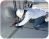
Installation of flashing should be completed in accordance with the manufacturer’s latest printed specifications. (Photo courtesy of Johns Manville.)
The material selected should have an in-service life expectancy that meets or exceeds that of the membrane. This is an important characteristic because the flashing generally has to perform in more severe conditions than the membrane. The selection of inferior materials to save money up front can result in severe economic losses due to premature failures.
If the flashing material specified does not conform with the roof system and the surface that it is attached to, then even the most detailed flashing plans will fail. It is essential that this material is compatible with all adjoining materials and that it has the capability and durability to last the lifetime of the system. All flashing materials should be reinforced and impermeable to moisture infiltration from rain, snow, ice or ponding water. The flashing material must meet the requirements of the membrane manufacturer.
The material must also have the ability to withstand all thermal- and load-induced movements. An allowance must be made for differential movement between the membrane and all other parts of the application. Base flashing should not be anchored to parapet walls, unless the parapet and the substrate are continuously connected and cannot expand or contract independently. Counterflashings should not be connected to base flashings unless the possibility of relative movement between them can be positively prevented. If the flashing material cannot sustain the strains of roofing system movement, cracks and tears will develop and deteriorate the flashing.
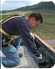
A technician applies bituminous flashing at a parapet wall. (Photo courtesy of Johns Manville.)
A critical component of proper vertical flashings is the principle of elevation. Vertical flashings must be a minimum of 8 inches above the completed roof surface. This height has become the industry standard and is recognized by most membrane manufacturers. The 8-inch height prevents water from pouring over the top of the flashings into the building or system. Additionally, this height allows enough clearance for the installation of cant strips in BUR systems.
Maximum vertical flashing height is also a consideration in proper flashing installations. Because flashings are manufactured with reinforced materials, the flashing material weight is an issue in vertical applications. Most manufacturers provide maximum allowable flashing heights for their systems. The weight also mandates that a top termination application be completed to prevent the material from sinking, slumping or buckling. Termination can be achieved with termination bars applied within an inch of the top flashing surface or metal counterflashings. The terminations should be secured to the flashing substrate with the appropriate fasteners applied at a rate of one fastener every 6 to 8 inches.
Perimeter Edge Flashing Details
Edge flashing is the most critical component of a roof system, particularly in high-velocity wind regions. The majority of wind damage and roof blow-offs are initiated at the perimeter edge. Flashing application at these points should be compliant with ASCE requirements. It can also be beneficial to review FM Loss Prevention Data Sheet 1-49, “Perimeter Flashing,” for valuable design and application techniques at these vulnerable locations.
Perimeter edge flashing typically begins with some form of perimeter blocking system. The base blocking should be applied to the structural components - not the decking. The blocking system is required for securement of the metal edge coverings. The membrane is typically applied through to the edge of the blocking with the flashing applied from the fascia to 4 inches to 6 inches onto the membrane surface. Some single-ply systems do not require separate flashings.
Gravel stops are applied at the perimeter edge. Fabricated from heavy or light metal, gravel stops are designed to cover the face of the edge and extend out onto the membrane surface. Flashing application depends on the type of metal used. Heavy metal gravel stops are applied over the flashings and secured to the blocking system with appropriate fasteners at the rate required for the buildings wind zone. Heavy metal gravel stops require concealed cleats and expansion joints for expansion and contraction.
Separation of the metal and the membrane are required in lighter metal applications. Flashings are typically applied over the metal in these cases. Some thermoplastic manufacturers require a thermoplastic-coated metal gravel stop is applied with their systems. In these applications, the gravel stop is heat welded to the membrane.
Penetration Flashing Details
It is imperative that penetration flashing is completed in accordance with the manufacturer’s requirements and proper roofing procedures. Large penetrations typically require the application of a raised curb. Flashing applications on curbs follow the principles of vertical flashings with the mechanical covering used as the counterflashing. Smaller openings require pitch pockets, which are fabricated from metal and filled in with grout and sealers.
Pipes, vents and stacks are typically field wrapped with a material compatible to the membrane system. Sealing of these materials is accomplished using the manufacturer’s approved adhesives and clamping devices. Many thermoplastic manufacturers provide prefabricated thermoplastic pieces for use at corners and penetrations. Application of these materials is completed by heat-welding the pieces to the membrane.
Flashing problems account for the majority of roof leaks on low-slope built-up roof systems. Proper flashing design is the responsibility of the roof designer. Adequate research of flashing conditions and the use of proper flashing details is vital to the long-term success of the roof system. Although design is usually not the responsibility of the contractor, awareness of proper details for all types of situations is required to ensure the required installation procedures are completed. This will eliminate flashing problems and costly callbacks, which will satisfy the designer and owner and add to the bottom line.

Report Abusive Comment