
John
A. D’Annunzio
The recent increase in the frequency of high-velocity wind events is prompting changes in the roofing industry. Attachment procedures for all roof systems - both steep slope and low slope - are being scrutinized, and code changes are imminent. Stringent building codes and tightened regulations were enacted in South Florida after Hurricane Andrew in 1992. The result of the recent surge of storms in Florida and the Gulf Coast over the last few years and the devastation they produced will mean more code changes regarding high-wind performance.
Some codes have already been altered to reflect the need for increased attachment methods. One of the codes altered involves the type of metal fabricated for use at the roof perimeter. The perimeter is the most vulnerable point of a roof in high-velocity wind events. Winds create negative pressure, which can lift the membrane and roof insulation loose from points of attachment. Wind uplift is severe at the roof perimeter, especially at corners, where it exceeds the normal static pressure against the wall. As air mass from the wind transcends the building’s perimeter, it forms vortices and creates uplift damage as it flows over and around the building.
Proper attachment procedures are required at all phases of roof perimeter construction. At the design phase, perimeter design calculations should be completed to determine proper fastening procedures at the most vulnerable point of a roof system to wind damage. At the construction phase, perimeter attachment inspections can be completed to ensure proper materials and securement procedures are completed. The base layer of the perimeter blocking must be attached to the structural component with approved fasteners and fastening methods. The fastening pattern of the perimeter metal must be in compliance with the perimeter fastening calculation completed for the specific project. Enforcement of these procedures can be completed at the local municipality level by tying them into the permit process. This method has proved to be effective in the South Florida Building Code since 1993.
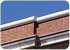
Many
municipalities have adopted the ANSI/SPRI ES-1, which defines edge securement
requirements for low-slope roofs. (Photo courtesy of W.P. Hickman.)
ANSI/SPRI ES-1
Technology must also continue to improve to employ materials and perimeter systems that are more resistant to high-velocity winds. In this area, the codes have been modified. There were no perimeter edge standards prior to 1980 when FM Global created a system of standards and approvals for use on FM Global-insured properties. The design community adopted this system because there were no other standards available at the time. FM Global standards were followed for roof attachment to decks and attachment of perimeter edge systems.In 1998, the association representing the Single Ply Roofing Industry (SPRI) developed three tests that are used to judge the quality and durability of perimeter metals at the fascia and coping areas. These tests were incorporated into the International Building Code (IBC) in 2002 and for the 2003 ICC revision, which was completed with input from FM Global, SPRI and the American National Standards Institute (ANSI). The code standard is referenced as ANSI/SPRI ES-1 and included in the ICC code as number 1504.5. It states: “Edge securement for low-slope roofs: Low-slope membrane roof systems metal edge securement, except gutters, installed in accordance with ANSI/SPRI Es-1 except the basic wind speed shall be determined from Figure 1609.”
At this time, most states and many municipalities have adopted the code. The intent of the code is to ensure that the design and installation of roof edge metals and copings meet specific criteria including material specifications, wind resistance of the edge metal and the structural integrity of the substrate that anchors the edge metal (i.e., nailers, etc.). The key elements considered in determining the loads on the roof edge are:
- Wind speed.
- Occupancy.
- Building height.
- Location of the edge material.
- Building location.
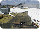
Perimeter
attachment procedures have been under increased scrutiny since hurricanes
Charley and Ivan, especially after studies conducted in the aftermath of these
storms by the Roofing Industry Committee on Weather Issues pointed to the
perimeter as the most vulnerable point in many roof failures. (Photo courtesy
of RICOWI.
ES-1 Test Methods
There are three test methods required under ANSI/SPRI ES-1. They are:- RE-1: Roof Edge Termination Test.
- RE-2: Pull-off Test for Metal Edge Flashing.
- RE-3: Pull-off Test for Metal Wall Coping.
The metal system applied at roof edges and wall copings must pass these tests for ES-1 certification. The test methods as defined by the standard are completed in the following manners.
RE-1 tests the roof edge termination for mechanically attached and ballasted roofing systems. The RE-1 test evaluates the perimeter attachment to ensure that it meets a minimum holding power of 100 pounds per foot. The membrane is pulled at a 45-degree angle to the roof deck to stimulate a billowing membrane. Failure is defined as any event that allows the membrane to come free of the edge termination or the termination to come free.
RE-2 is a pull-off test for metal edge flashing. It evaluates the strength of the metal edge flashing to ensure that the fascia system meets or exceeds the building’s calculated design wind pressure. A load is applied to the fascia metal, stimulating wind load on the fascia. The calculation used is: Force at failure X face = blow-off resistance. The results must meet or exceed the calculated design pressure of the building.
RE-3 is a pull-off test for metal wall coping. It evaluates the strength of the metal coping cap to ensure that it meets or exceeds the building’s calculated design wind pressure. A load is applied to the coping cap, simulating wind load. Simultaneous up and out forces are used. The calculations used to determine the blow-off resistance for the top, face leg and back leg are: Force at failure X surface area = blow-off resistance.
The results must meet or exceed the calculated design pressure of the building.
What Does the Code Mean?
All metal edge flashings must meet the test requirements. For roofing contractors, the code basically eliminates shop (or field) fabrication of metal edge flashings and metal copings in municipalities that that have adopted ANSI/SPRI ES-1 (unless they have been tested and approved). At this time, most states and many municipalities have adopted the code. Best practice is to check local codes for all projects.For designers, it implies that perimeter edge calculations and wind engineering are required to determine the perimeter edge design pressure. Design of perimeter edge and metal copings should be in compliance with ANSI/SPRI ES-1.
For metal edge manufacturers, the code requires approved testing and certification of all metal edge flashings and metal copings. Manufacturers that do not meet the compliance standards of ANSI/SPRI ES-1 will not be allowed on facilities in municipalities that have adopted the code.
The intent of the code is to reduce roof damage and limit associated human health and safety risks from high-velocity wind events. The code provides a standard for metal fabrication, securement and attachment methods - the key factors in proper edge termination. These code changes will not eliminate all wind related roof damage, but they will greatly reduce damage initiated by improper attachment methods. The success rate of the code will ultimately be based on verification through enforcement.


Report Abusive Comment